 Skip to main content


Developing a utility-scale solar facility requires a structured, multidisciplinary engineering framework. For utility-scale solar power plant design, building a high-performing solar asset involves coordinated technical expertise across energy system modeling, civil and structural engineering, Solar DC system design, Solar AC system design[PG1] [SK2] [SK3] , automatic control systems, and high-voltage grid integration.
Whether designing a few MW developments or multi-gigawatt solar plants, detailed Solar power plant engineering is critical to the energy produced, capital costs (CapEx), operation costs (OpEx), and overall life cycle ROI (ROI). This utility-scale solar power plant design guide provides an overview of the engineering lifecycle: site selection, solar plant layout design, electrical design, solar SCADA system integration, power system studies for solar PV, and grid interconnection for solar plants.
Utility-Scale Solar Plant Engineering Workflow
Utility-scale solar projects, ranging from a few MW developments to multi-gigawatt solar plants, require a structured, multidisciplinary engineering process. Each engineering decision can influence project cost, schedule, energy yield, grid compliance, long-term reliability and overall asset bankability.
Accelerated engineering decisions or inadequate site verification can increase capital risk, cause grid-interconnection delays and lead to costly design changes during construction or operation. The following is a breakdown of the multidisciplinary engineering workflow done throughout the life of the project.
Site Selection
To minimise civil site preparation costs, initial site evaluations examine physical and environmental constraints. Long-term satellite irradiance data provide baseline solar resource modelling. Geographic Information Systems (GIS) and topographical mapping delineate site boundaries, slope contours, and potential shading obstacles.
On-site evaluations also assess the proximity and accessibility of grid substations, transmission infrastructure and transportation networks. Civil engineering assessments verify that site access roads can accommodate heavy construction and equipment transport. Electrical routing studies evaluate power evacuation feasibility, transmission-line corridor requirements, land levelling and grading scope, and the optimisation of medium-voltage feeder lengths to reduce I²R losses.
Feasibility Study
Once the suitable site is identified, a detailed solar feasibility study validates technical and commercial viability. Long-term energy yield assessments are developed using P50/P90 scenarios to support financial modelling, investment decisions and lender due diligence.
Geotechnical field studies determine the soil load-bearing capacity, soil resistivity, and required post-embedment depths. Hydrological and drainage studies assess site-specific design storm events and applicable flood return periods to establish equipment elevations, drainage requirements, grading limits and flood protection measures. Power flow studies evaluate grid capacity at the point of common coupling (PCC) to confirm grid substation readiness and power evacuation feasibility.
Concept Design
Concept design considers technical parameters and systems to reduce the Levelised Cost of Electricity (LCOE). Structural trade-off analyses compare fixed tilt mounting structures against single-axis tracking systems based on geographical coordinates, solar resource data, and direct normal irradiance (DNI).
Electrical layout optimisation evaluates inverter topology (centralised versus string) and optimises array block layouts. Optimising inverter and transformer locations within array blocks can reduce DC cable lengths, electrical losses and cable costs while maintaining practical access and maintenance requirements.
Detailed Engineering
Solar plant detailed engineering translates the approved concept design into construction-ready engineering documents covering civil, structural, electrical and control systems. Engineering teams finalise array configurations, perform structural and mechanical load calculations, develop cable routing and equipment layouts, and prepare Single Line Diagrams (SLDs) and other detailed design drawings.
In the detailed engineering package, the project BOQ, equipment ratings and specifications, medium-voltage collection system and feeder layouts, protection philosophy, and protection relay settings are developed and finalised for construction and installation. The package also includes the calculations, drawings, schedules, and technical specifications required for procurement, construction, testing, and commissioning.
Procurement Support
Procurement engineering ensures hardware sourcing complies fully with technical specifications and international standards.Technical procurement specifications and equipment schedules are prepared for PV modules, tracking systems, central or string inverters, step-up transformers and balance-of-plant (BOP) equipment.
Commercial and technical bids are compared with vendor proposals for efficiency, thermal derating, warranty periods, and cost. After vendors are selected, engineering teams review factory drawings and design parameters for ease of field installation.
Construction Support
Engineering oversight continues throughout civil and electrical installation to address field variables. If unexpected subsurface conditions are encountered during pile installation, structural foundations are re-engineered to prevent schedule delays.
Field inspections verify foundation pile embedment depths, PV module mounting alignment, cable trench profiles, conductor bend radii, and terminal connection torque values to ensure compliance with design specifications.
Testing & Commissioning
System commissioning verifies safety and grid readiness prior to energisation. Cold commissioning includes insulation resistance, continuity, grounding, PV array verification, transformer testing and other equipment-specific tests in accordance with applicable IEC/IEEE standards and project specifications.
During hot commissioning, the plant is synchronised to the grid. Power Plant Controllers (PPCs), automatic control systems, and protection schemes are tested in real time to assess dynamic responses to frequency variations and grid disturbances.
O&M Handover
The final phase transfers the operational asset to the plant owner or operations team. Handover packages include as-built drawings, operations manuals, equipment warranty documentation, and initial benchmark performance test results.
Integrated SCADA monitoring platforms are linked to central management systems and provide real-time telemetry, performance ratio (PR) monitoring, and predictive maintenance capability from the day the plant is installed.
Partner with Our Engineering Team
At utility scale, the balance between energy yield, civil development costs, electrical losses and overall lifecycle cost must be optimised. Employing a solar EPC engineering team from an industry leader ensures project bankability, regulatory compliance, and maximum asset life.
Overview of Utility-Scale Solar Plants
Solar power plants in utility-scale deployments from a few MW developments to multi-gigawatt solar plants, with power delivered as a whole to high-voltage transmission lines. While the majority of installed PV systems are on the ground, floating PV (FPV) installations on reservoirs and water bodies are becoming more common.
Technology Choices: Fixed-Tilt vs. Trackers
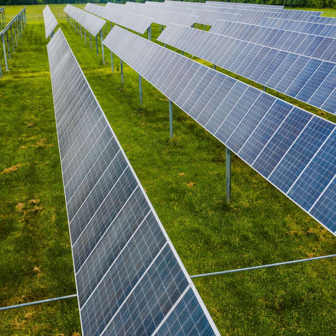
● Fixed-Tilt Systems: A lower capital investment and a lack of moving parts, but a high periodic cost. They are most often used in areas of high wind loads, steep surfaces, or difficult geotechnical conditions.
● Single-Axis Trackers: Rotate module arrays along a single axis to track diurnal solar movement, substantially boosting overall annual energy yield. Recommended for regions with high Direct Normal Irradiance (DNI), though they involve higher initial CapEx and scheduled mechanical maintenance.
Partnering with a qualified solar PV plant design consultant or a Utility-Scale Solar Consultant India, will ensure that the hardware selection is based on the location’s environmental conditions and the expected return on investment for the project.
Solar DC System Design
The solar DC system design covers all components from the individual PV cells to the DC input terminals of the central or string inverters.
Cable Sizing, Protection, and Standards
● DC Conductor Sizing: Cable cross-sections are selected based on ampacity, environmental derating, installation conditions, allowable voltage drop, thermal performance and the project’s electrical loss budget. A project-specific voltage-drop target is established during detailed design.
● Combiner Boxes & Circuit Protection: String combiner boxes include string fuses for reverse current protection, DC isolation switches, and Type II Surge Protection Devices (SPDs).
● Earthing & Lightning Protection: An array’s equipotential bonding and lightning protection schemes must comply with IEC 62561 and IEC 62305.
● Conformity with International Standards: System architectures are compliant with IEC 61215, IEC 61730, IEC 62548, IS, and NEC Article 690.
Read our comprehensive technical guide on Integrated Solar PV Engineering to evaluate how DC design integrates with overall plant electrical architecture.
Solar AC System Design
The solar AC system design converts the inverter’s low-voltage output to medium and high voltage for transmission over long distances.
● Configuration of the inverter: Engineers evaluate the advantages of central inverters (higher power density, less maintenance) compared to decentralised string inverters (higher MPPT resolution, more local fault isolation).
● MV Collection: Designing underground or overhead collection networks of 11 kV, 22 kV, or 33 kV to feed block step-up transformers (LV/MV) into the main pool substation.
● Design & Structure of Substation and Switchgear: Selection of indoor/outdoor MV switchgear, vacuum circuit breakers (VCBs), Main Power Transformers (MPTs), and dynamic reactive power compensation units (STATCOMs or switched capacitor banks).
● Voltage Drop & Power Quality: Conductor size keeps total AC voltage drop below 1.0%–1.5%. Power-quality studies assess harmonic distortion and other power-quality parameters at the PCC against applicable grid-code and IEEE 519 requirements.
For more information on electrical balance of plant execution, check out our related document, Detail Engineering.
SCADA & Monitoring System
A solar SCADA system is used to monitor and report continuous data acquisition, remote plant control, and real-time monitoring of the plant performance and grid compliance.
Core Features of Utility Solar SCADA
● Real-Time Telemetry Acquisition: Real-time telemetry acquisition (sub-second samples of string currents, inverter status, transformer temperature, and circuit breaker positions).
● Meteorological Station (MET) Integration: Plane-of-Array (POA) pyranometers, Global Horizontal Irradiance (GHI), ambient temperature sensors, module back-sheet sensors, and anemometers for automatic tracker stow protection.
● Active & Reactive Power Control: Execution of local Load Dispatch Center (LDC) commands to manage active power curtailment and dynamic power factor using a centralized PPC.
● Analytics & Maintenance Management: Automated calculation of real-time PR, detection of localised string underperformance, and data integration for predictive maintenance workflows.
Grid Interconnection Requirements
Connecting grid interconnection for solar plants is subject to strict compliance with TSO grid codes and utility regulations.
| Grid Requirement | Key Objective | Technical Mechanism |
| Fault Ride-Through (FRT) | Plant stays connected during grid disturbances | Low Voltage Ride-Through (LVRT) & High Voltage Ride-Through (HVRT) capability |
| Frequency Response | Supports grid frequency stabilization | Frequency-response functions may include active-power droop control, frequency-watt response and other grid-code-specific control functions |
| Reactive Power Support | Maintains grid voltage stability | Dynamic VAR injection/absorption via inverters or STATCOM units |
| Protection Coordination | Isolates faults fast without dropping the whole plant | Protection schemes may include overcurrent, transformer differential, feeder protection, distance protection where applicable, anti-islanding functions, breaker failure protection and utility-specific protection requirements. |
Executing early Grid Integration Studies identifies utility requirements early and avoids delays during final plant commissioning.
Power System Studies for Solar PV
Power System Studies for solar PV using software (ETAP, DIgSILENT PowerFactory, PSS/E) are required for utility grid synchronisation:
● Load Flow & Voltage Drop Analysis: Verifies continuous steady-state bus voltage profiles and thermal loading limits across all operating conditions.
● Short Circuit Calculations: Determine symmetrical and asymmetrical prospective fault currents per IEC 60909 to establish switchgear interrupting ratings.
● Protection Coordination: Establishes the time-current characteristic (TCC) curves and pickup thresholds for relays, circuit breakers, and fuses to ensure selective fault isolation.
● Harmonic & Power Quality Analysis: Models voltage and current total harmonic distortion (THD) to verify compliance with IEEE 519 limit values.
● Arc Flash Risk Assessment: Calculates incident energy per IEEE 1584 to determine the limit and PPE requirements for personnel safety.
To examine analytical modelling methods, refer to our complete technical manual on Power System Studies.
Engineering Deliverables & Documentation
The utility-scale solar engineering package includes calculations, layout drawings, and technical schedules for civil, structural, electrical, and control engineering fields.
Electrical & Control Documentation
● Single Line Diagrams (SLD)
● DC & AC Cable Schedules
● Earthing & Lightning Calculations
● Protection Relay Settings
● SCADA Network Architecture
● Master Bill of Quantities (BOQ)
Civil, Structural & Mechanical Documentation
● Site Topography & Grading Plans
● Structural Foundation Calculations
● Module Mounting Structure (MMS) Drawings
● Drainage & Internal Road Plans
● String Layouts, Structural Foundation & Civil Drawings
● Solar Plant Layout & Array Drawings
For asset owners, a Solar engineer provides independent technical oversight, design review, and quality control on the project to protect their investment over the long term.
Summary
Utility solar projects require rigorous engineering execution in all phases, from initial site assessment and layout optimization through AC/DC system design, SCADA integration, and power system modelling. Reliability of engineering enables a lower balance of system costs, grid code compliance, and lifetime asset profitability.
If you are seeking technical engineering support for upcoming renewable assets, review our Renewable Energy Consulting services.
Frequently Asked Questions
How are power losses minimized?
Power losses can be reduced by optimizing the cross-sections of conductors to reduce the DC/AC voltage drop below 1.0%, placing inverter stations centrally on the sub-arrays, selecting low-loss transformers, lowering the tilt and pitch of the array to minimize shading between adjacent arrays, and aligning string voltages.
What approvals are required before construction?
The types of regulatory approvals typically required are Environmental Impact Assessment (EIA), land-use conversion permits, civil construction permits, utility grid interconnection approvals, power evacuation clearances, and aviation/defence clearances where applicable.
What is a utility-scale solar power plant?
Utility-scale solar power plants are large photovoltaic power plants ranging in size from 5 MW to over 1,000 MW. They supply large quantities of electricity directly to the high voltage transmission grid through a Power Purchase Agreement (PPA) or merchant agreement.
What is included in a solar plant feasibility study?
A feasibility study combines solar resource estimates (GHI/DNI), topographical and geotechnical surveys, civil and electrical layout design, interconnection capacity estimates, a financial model, P50/P90 energy yield estimates, and environmental impact studies.
How is the layout of a solar PV plant designed?
We design plant layouts using 3D civil modelling tools to evaluate contours, rows-to-row shading limits, locate centrally located inverter stations, and map internal road and drainage networks to maximise the generation potential while minimising civil earthworks.
What is the difference between DC and AC system design?
DC system design includes everything from the PV modules to the inverter DC inputs, such as string sizing, DC cabling, combiner boxes, and DC surge protection. AC system design includes everything from the inverter AC output to the grid coupling point, such as step-up transformers, MV collection networks, switchyards, and high-voltage substations.
Why is SCADA important in utility-scale solar plants?
SCADA platforms enable real-time monitoring, active and reactive power control, grid code observance, fault isolation, and predictive maintenance within the facility.
What power system studies are required before grid connection?
Electric utilities must typically perform load flow, short-circuit calculations (IEC 60909), coordination of the protection relay, harmonic analysis (IEEE 519), dynamic transient stability, voltage stability, and arc flash safety studies before grid synchronization can be approved.
What standards are used for Solar PV Plant Engineering Services?
Key international standards include IEC 62548 and IEC 60364 (PV array design), IEC 61215 / IEC 61730 (Module qualification and safety), IEC 62109 (Inverter safety), IEEE 519 (Harmonics), IEC 60909 (Short-circuit currents), IEEE 80 (Substation grounding), and regional grid codes.
Why is the owner’s engineering important for utility-scale solar projects?
Owner’s Engineering experts provide technical oversight, review EPC design packages, oversee construction quality, check technical specs, and protect the asset owner’s financial investment throughout the life of the project.
